"Corrections"
The fuel correction settings are bundled in the corrections window, which itself is devided into several panes also.
Top of Page
"Warm Up"
This tab contains tables, which mainly keep data for fuel adjustments regarding to engine temperature.
The most common table will probably be the warmup enrichment table,
accompanied by the front cylinder correction and the idle correction, which is similar to the warmup correction, but active in idle only.
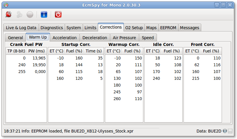
Click image for an unscaled view
- Crank Fuel PW
- This table defines the base "Crank Fuel Pulsewidth", related to load, which is used while the
engine is cranking. The resulting fuel pulsewidth is this base value, multiplied with the "Startup Correction",
the "Warmup Correction" and the "Air Temperature Correction" (all in percent),
and the "Battery Voltage Correction" added as
a last step.
- Startup Correction
- These tables defines the fuel enrichment, applied directly after the engine has started. Engine temperature is the key value,
shown in the leftmost column.
The "Startup Correction" is a temperature dependent enrichment,
applied over a specific timespan (in seconds), as set in the "Startup Duration" column.
- Warmup Correction / Idle Correction
- After the startup duration has exceeded, the "Warmup Correction" will be applied, until the engine
reaches it's operating temperature (about 160 °C, 320 Fahrenheit). When the engine is in idle,
the "Idle Correction" will be used instead.
- Front Cylinder Correction
- This correction will be applied on the front cylinder only, probably to compensate a different heat flow between the two cylinders.
Top of Page
"Open Loop"
If no feedback from the exhaust gas O2 sensor is used to control fueling, the engine is operating in open loop. In this case special
corrections are used to adjust the amount of fuel injected.
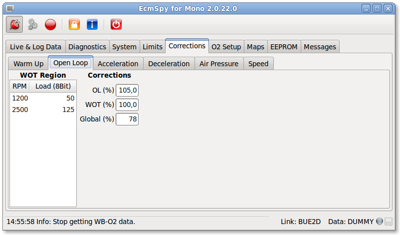
Click image for an unscaled view
- WOT Region
- The WOT (wide open throttle) region is above the boundary described in the WOT region table.
The line is extended from the two points to the left or right edge of the fuel or spark advance map. The WOT region is marked by a black
line in the fuel maps.
- OL Correction
- Open loop correction is active for every operating point that is outside the closed loop, idle closed loop or WOT area. The closed loop
region is surrounded by a red line in the fuel maps.
- WOT Correction
- WOT enrichment gets activated, when the engine operating point is above the WOT boundary as defined by the WOT region table.
- Global Correction
- Global correction is a feature available for DDFI-3 typ ECM only.
Gobal correction is active everywhere on the map, it's shifting all map values up or down.
The other corrections are applied additionally if required.
Top of Page
"Acceleration"
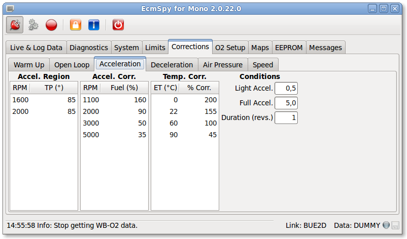
Click image for an unscaled view
This tab holds all the tables that are related to the acceleration enrichment.
- Acceleration Region
- The region where acceleration correction will be applied.
The line is extended from the two points to the left or right edge of the fuel or spark advance map.
- Acceleration Correction
- The acceleration correction table defines the maximum amount of fuel added.
The real amount depends on engine temperature, the acceleration condition and throttle speed.
- Temperature Correction
- Because of wall wetting the acceleration correction requires to be temperature corrected,
the corrective values are shown in this table.
- Light / Full Acceleration Condition
- A light or full acceleration condition exists, when the actual throttle position
less the filtered throttle position exceeds the value shown (in degree * 10).
The acceleration enrichment is first multiplied with and then added to the fuel pulsewidth.
With a light acceleration, a percentage of the temperature adjusted enrichment is used,
based on the speed of throttle movement. In a full acceleration, 100% of the temperature corrected
enrichment will be added. If the full acceleration condition value is less than 128, the amount of fuel is also
injected on the opposite injector at the same time.
- Duration
- The number of crankshaft revolutions the acceleration correction lasts.
Top of Page
"Deceleration"
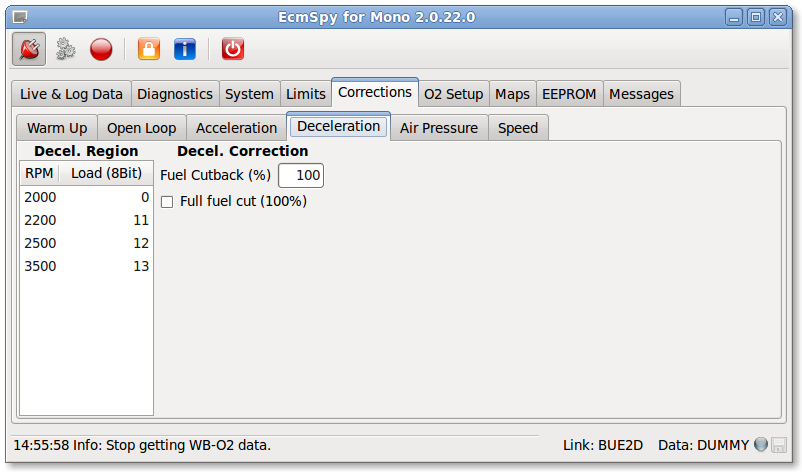
Click image for an unscaled view
All settings that define the deceleration correction are shown here.
- Deceleration Region
- This table defines the deceleration region. Engine operating points below this boundary trigger a deceleration correction.
Contrary to the acceleration region, this line is not extended to the edges of the fuel map.
- Fuel Cutback
- The amount of fuel provided during a deceleration conditon.
- Full Fuel Cut
- If this checkbox is marked, fuel will be cut completely in a deceleration condition.
Top of Page
"Airbox Pressure Correction"
Many ECM types (DDFI-2 and DDFI-3) support a barometric correction, which can be switched on when an air pressure sensor is
installed (all 1125 models have a barometric pressure and a manifold absolute pressure sensor installed already).
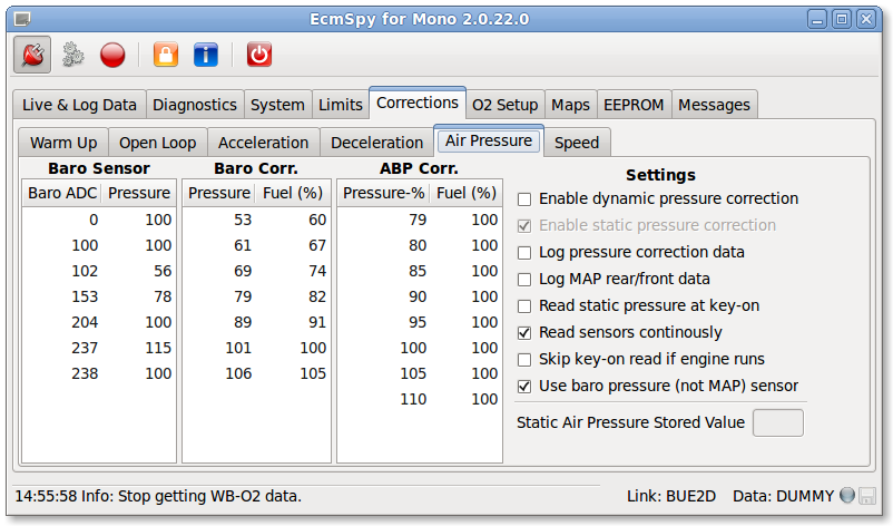
The air pressure correction feature consists of two parts: a static barometric pressure correction and a dynamic airbox pressure correction.
The static pressure correction ("Baro Correction") is calculated directly after the ignition is switched on.
The key-on air pressure can be read from one of two sources, depending on the settings: either from a stored value in the EEPROM or from
the pressure sensor. The key-on air pressure is used to calculate the static air pressure correction. The static correction does
not change while riding,
so later air pressure changes (e.g. due to altitude changes) will not be compensated. The static barometric pressure serves as
a reference for the dynamic airbox pressure correction ("ABP Correction"), which is calculated and applied
continously while riding.
- Baro Sensor
- This table describes the hardware, the signal voltage (in 8-bit resolution, 0 = 0 volts, 255 = 5 volts)
as a function of air pressure (also in 8-bit resolution). As the pressure value allows a range from 0 to 255 only,
the pressure could be entered in kilopascal (kPa) units (ISO 10780 standard air pressure = 101.3 kPa) for convenience.
Theoretically any, even virtual units, can be used, if they fit the 8-bit value range,
but all successive tables must be adjusted to this units.
The first and the last row of the table define the values used in case a sensor error (under- or overvoltage)
occurs.
- Baro Correction
- The baro correction table is used to retrieve the air pressure correction for the static air pressure, calculated
at key-on and stored in the EEPROM. The static air pressure is assumed not to change while riding.
- ABP Correction
- The dynamic pressure correction evaluates the pressure sensor signal continously and calculates the percentage
of the current airbox pressure compared to the static air pressure. This percentage is used to look up
the correction in the right column of the baro correction table.
|
-
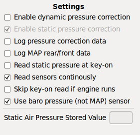
Pressure Sensor Settings:
-
- Enable dynamic pressure correction
- Enable the airbox pressure feature and start evaluating dynamic pressure sensor data (for DDFI-2:
"Enable Baro Feature" is required to be enabled also).
- Enable static pressure correction
- Enable the pressure sensor input and start evaluating static pressure sensor data at startup (DDFI-2 only).
- Log pressure correction data
- Log barometric and airbox pressure correction for fuel (dynamic correction is stored in "Flags 6",
static correction in "Flags 5").
- Log MAP rear/front data
- Log manifold absolute pressure data (DDFI-3 only).
- Read static pressure at key-on
- When activated, the air pressure sensor is read at key-on and it's value used for the static air pressure correction.
Otherwise the value stored in the EEPROM will be used. A new value is written to EEPROM at each startup, when this
feature is enabled.
- Read sensors continously
- Pressure sensor data will be read and evaluated continously.
- Skip key-on read if engine runs
- Do not read and use pressure sensor data at key-on, if the engine is already running.
- Use baro pressure (not MAP) sensor
- Use the baro pressure sensor instead of the manifold pressure sensor.
|
Top of Page
"Speed"
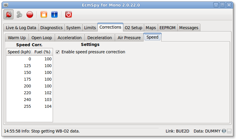
Click image for an unscaled view
To compensate for speed dependent air pressure changes (e.g. due to ram air effects for compliant intake designs)
the speed correction could be used if the dynamic air pressure correction is not activated.
- Speed Correction
- The speed correction table consists of the speed column (speed in kph) on the left and the according fuel
correction (in percent) on the right. The first and the last row contain values, that will be applied in case
of a sensor error (under- or overvoltage).
- Enable speed pressure correction
- Mark this checkbutton to activate the speed correction.


