"O2 Setup"
The O2 sensor setup window contains all O2 sensor related configurations,
sensor data as well as closed loop and calibration mode area definitions.
Top of Page
"Closed Loop"
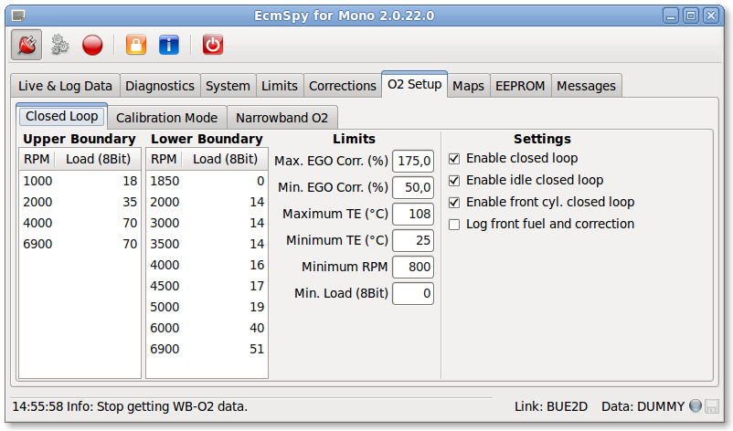
When the engine is operating in closed loop, the exhaust gas oxygen level is measured and fed back to the arithmetic statements, that
calculate fuel injection pulsewidth. This way, the fueling is adjusted that way, that it will be stoichiometric, for a good efficiency.
Click image for an unscaled view
- "Upper / Lower Boundary"
- Boundary (expressed as pairs of load and engine speed) of the closed loop area. The upper and lower boundary lines, as described in the tables,
are connected and then build a closed polygon, which surrounds the closed loop area. Each operating point that is inside this border
will be operating in closed loop (unless prevented by other engine conditions, e.g. engine temperature as shown below).
The RPM values must be in ascending order. This area is shown with a red border in the fuel maps.
-
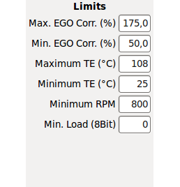
Mixture control can be inhibited by specific engine temperature or EGO correction conditions.
|
-
EGO Correction Limits
-
- Maximum EGO Correction
- Maximum allowed EGO correction in percent
- Minimum EGO Correction
- Minimum allowed EGO correction in percent
- Maximum TE
- Upper engine temperature threshold, above which EGO correction will be switched off
(enter -40 °C to disable threshold)
- Minimum TE
- Lower engine temperature threshold, below which EGO correction will be switched off
(enter -40 °C to disable threshold)
- Minimum RPM
- Engine speed threshold, below which EGO correction will be switched off
- Minimum Load
- Load threshold, below which EGO correction will be switched off
|
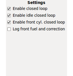
The EGO correction settings determine if and where fuel control will be active and if the front cylinder
will be controled independently, if supported by hard- and software.
|
- EGO Correction Settings
-
- Enable closed loop
- Switches fuel control and EGO correction on or off.
- Enable idle closed loop
- Enable EGO correction in idle (Enable Closed Loop is required to be enabled).
- Enable front cylinder closed loop
- Enable fuel control for the front cylinder (if appropriate hardware is installed).
- Log front fuel and correctionData
- Log EGO correction and other fuel values for the front cylinder instead of battery voltage correction,
warm up enrichment and air temperature correction.
(These front values are logged already by default, but at a different position.)
|
Top of Page
"Calibration"
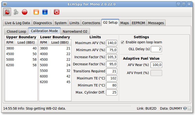
When the engine is entering the calibration, or Learning Closed Loop (LCL), mode area, the exhaust gas oxygen level is
evaluated to set up an adaptive correction,
the Adaptive Fuel Value (AFV), that is applied in all areas outside the closed loop areas.
Click image for an unscaled view
- "Upper / Lower Boundary"
- Boundary (expressed as pairs of load and engine speed) of the calibration or learning mode area. The upper and lower boundary lines,
as described in the tables,
are connected and then build a closed polygon, which surrounds the calibration mode area. Each operating point that is inside this border
will be operating in closed loop (unless prevented by other engine conditions, e.g. engine temperature as shown below) and also allow for
an updated AFV calculation.
The RPM values must be in ascending order. This area is shown with a blue border in the fuel maps.
-
AFV calculation can be inhibited by specific engine temperature or EGO correction conditions.
|
-
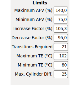
Calibration Limits
-
- Maximum AFV
- Maximum allowed AFV in percent.
- Minimum AFV
- Minimum allowed AFV in percent.
- Increase Factor
- If applicable, AFV will be increased by this percentage.
- Decrease Factor
- If applicable, AFV will be decreased by this percentage.
- Transitions Required
- O2 sensor voltage transition required to trigger an AFV change.
- Maximum TE
- Upper engine temperature threshold, above which calibration will be switched off
(enter -40 °C to disable threshold).
- Minimum TE
- Lower engine temperature threshold, below which EGO correction will be switched off
(enter -40 °C to disable threshold).
- Maximum Cylinder Difference
- Maximum allowed AFV difference between front and rear cylinder
(DDFI-3, with cylinder independent fuel control and appropriate hardware installed only).
|
|
-
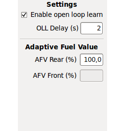
OLL and AFV settings
-
- Open Loop Learn (OLL) Delay
- "Open Loop Learn" is a protective measure of the ECM, to prevent the engine running lean
for too long even outside the closed loop. If the checkbox is marked, EGO is monitored and evaluated in open loop
constantly. If the O2 sensor continously indicates a lean mixture for a period longer than the "OLL
Delay" (in seconds), AFV will be increased by one step, as defined in the
"AFV Increase Factor" (see above).
- Adaptive Fuel Values (AFV)
- The rear and front (where applicable) AFV, as stored in the EEPROM.
To set the AFV, in case it has run amok and prevents the engine from starting, enter a new value here (preferably 100%),
then burn the adjusted eeprom.
|
Top of Page
"Narrowband O2"
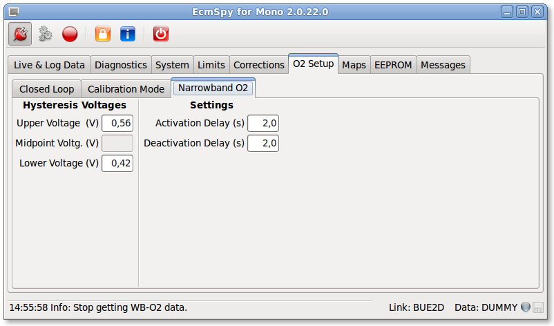
Click image for an unscaled view
|
-
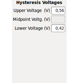
Hysteresis Voltages
- A narrowband O2 sensor is not capable to quantify the O2 level in the exhaust gas. Instead it qualifies the
exhaust gas oxygen level by working like a switch, and rapidly changing the emitted voltage when crossing the
stoichiometric oxygen level. This voltage jump (at least 0.5 volts for a working O2 sensor) is evaluated by the ECM.
To prevent the ECM from too many adjustment changes
when the sensor voltage is near the O2 sensor's midpoint voltage (0.5 volts), a voltage range on both sides of the midpoint
voltage protect the control circuit. Any sensor voltage between the upper and the lower hysteresis voltage is considered to
be erratic, and will not be taken into account for fuel control. Note: it is impossible for a working O2 sensor to
fix it's output to 0.5 volts.
- Upper Voltage
- The upper hysteresis threshold. A sensor voltage above the upper threshold indicates a rich mixture.
- Midpoint Voltage
- The midpoint voltage indicates an O2 sensor error, as i.e. a broken wire or an inactive/cold O2 sensor.
(DDFI and DDFI-2 only.)
- Lower Voltage
- The lower hysteresis threshold. A sensor voltage below the lower threshold indicates a lean mixture.
|
|
-
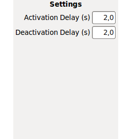
Activation Delays
- Activation Delay
- A delay that has to be exceeded before O2 sensor voltages will be evaluated
if the engine's operating point is within the activation area.
- Deactivation Delay
- A delay that has to be exceeded before O2 sensor voltages will be dissmissed
if the engine's operating point is outside the activation area.
|


