

The Connection between the PC and the Buell ECM happens via a special cable and plug. A direct connection is not possible due to the nature of the socket on the Buell ECM, which is different from a serial-type PC connector, and also because both systems have different voltage requirements which are not directly compatible.
As the traditional serial ports (RS232) have been widely replaced by USB ports, a USB convertor cable is required. A very large supplier of USB chips is FTDI, they offer a USB-to-TTL cable which works fine with the ECM and needs only the right plug fitted. Once installed, the driver software will be installed automatically (for Windows 7 and later), or can be downloaded from the FTDI driver's area for older Windows versions. The FTDI driver allows the EcmSpy software to directl connect to the USB port without using a virtual serial port, as all other brands require, and what often causes a lot of hassle.
You will often find cheap EcmSpy cables offered in the internet. Please do yourself a favour and get a well proven, although a bit more expensive, FTDI cable from a reliable source. Cable drivers and virtual serial ports can create a lot of problems and troubleshooting them will often need a considerable amount of your time. Only the FTDI drivers allow the EcmSpy software to directly connect to the USB port.
To connect to the ECM a special diagnostic cable assembly is required. The plug is manufactured by Deutsch IPD, a manufacturer of plugs and sockets. The plug consists of several individual parts:
There's also a clone available, manufactured by Ampheonl, with these part numbers:
Please use your favourite search engine to find vendors. Many large distributors will have these plugs in stock.
The converter cable's pinout is is available from the FTDI website. You will use the following wires from the wire-ended side of this cable to mate to the plug housing above (the numbers are printed on the back side of the Deutsch plug):
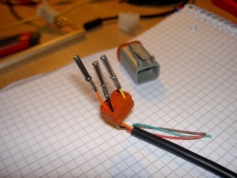
The assembly of the plug is not particularly difficult. Normal pliers for automotive connectors are not suitable, you must use special crimping pliers, although not necessarily those for Deutsch components. You can also solder the wires directly into the contacts if you are unable to find the correct crimping pliers. The plug assembly is shown on the following pictures, click on the picture to open a larger view in a new browser window.

Click image for an unscaled view

Click image for an unscaled view
Strip the three wires from the FTDI USB cable if required: Yellow (send), Orange (receive) and Black (ground). The remaining three cables are not used and can be taped off or cut flush and taped to prevent damage to the PC USB port. I strongly advise to fold over half of the stripped wire onto itself before inserting it into the connector. This effectively doubles the gauge of the wire and ensures a tight fit. Then, slide the contacts over the cable and crimp or solder.

Click image for an unscaled view
Crimping could be done with a allmost any heavy duty crimping pliers (e.g. end sleeve crimpers), but take care to not deform the connector end. If you do not own such a tool, soldering may be the best option. Make sure the wire and connector are throughly cleaned with denatured alcohol to minimize contamination. Heat the center of the connector with the iron until hot, then feed in the solder for a strong joint.

Click image for an unscaled view
The finished contacts are threaded through the seal. Be careful how these are inserted as this will determine the pin-out of the final plug. The correct sequence is shown below (all positions listed are viewed from the back with the clip facing up).

Click image for an unscaled view
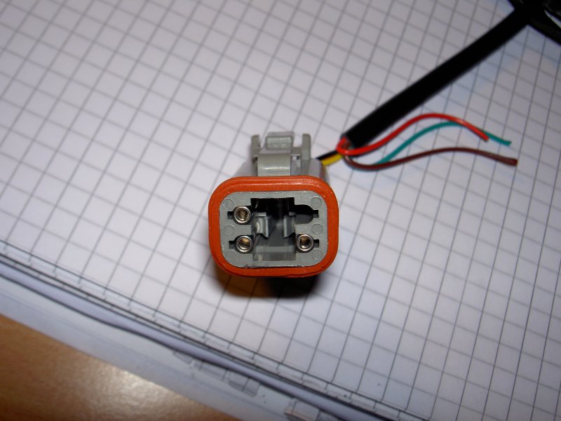
Now insert the seal and contacts together into the plug body. The clip of the plug must be up as shown in the picture above. Make certain that the contacts are pushed completely through until they contact the front of the housing. If necessary, use a bent paper clip pushed through the back of the plug to help. Ensure that the clip housing engages completely into the plug. You should here a click. Pull gently on the assembly to make sure the connection is solid.

Click image for an unscaled view
The last step is to press the clip from the front into the plug. This will keep the contacts in place in the event that the plug is separated and locks the contacts into the plug so they will hold the plug seal in position.

Click image for an unscaled view
Here again is the back of the finished plug and the correct position of the individual cable colors. If the contacts have been assembled in a wrong position, then the orange clip can be pulled out of the plug body and the contact unlocked of with a needle or small screwdriver.
The entire assembly procedure takes approximately five minutes.
Using a piece of wire or a paper clip, short-ciruit the PC transmit (pin 1, orange wire) and PC reveive (pin 3, yellow wire) contacts of the Deutsch plug. The pin numbers are stamped on the wire (backward) side of the plug housing. Plug the cable into the PC and start the EcmSpy application. Next try to connect to the ECM. If the cable is working properly, a message will pop up, telling that an error has occured and the cable is probably short-circuited:

If this message is displayed, the cable can be safely assumed to work properly. In all other cases, check hardware and software (e. g. drivers) according to the cable vendor's specification.
Many thanks to Daniel for translation.